Power source

Nations 280XP wiring diagram

See the Nations 280XP connection points and wiring example. Open the diagram in Crimp to add your equipment and plan the cables between them.

Open this example as a new project. Use your own parts and cable lengths to make the plan yours.

Cable sizing for this example

Use the diagram as a starting point for your installation. Replace the example equipment and cable lengths with your own, and check the connections against your exact model's instructions.

10 ft one way

12 V system

Wire
3/0 AWG · 95 mm²
Example fuse
350 A
Design current
280 A
Voltage drop
2.6%

Sized against ABYC E-11. The design current is the unit's rated output. The length is one way; voltage drop includes an equal-length return.

Run-length and manufacturer assumptions

The editable example uses 3.048 m (10 ft) runs unless a shorter run is stated. Metric overviews round these to 3 m. Adapt the parts and lengths to your installation before choosing cable and protection.

Show sizes in mm²

Wiring diagram

How the 280XP 280A is wired.

Open this example in Crimp to use your own parts and cable lengths. Review the assumptions and installation notes as you adapt the circuit.

Nations 280XP wiring diagram, 3/0 AWG (95 mm²) positive feed protected by a 350 A fuse and a matching negative return between the 12 V battery bank and the unit.
Edit this wiring example

Installation notes

Connections and installation requirements.

Guidance for this model, with sources linked beside the relevant advice.

Verified against the manufacturer's documentation, checked 2026-08-27. Manufacturer documentation →

What it does

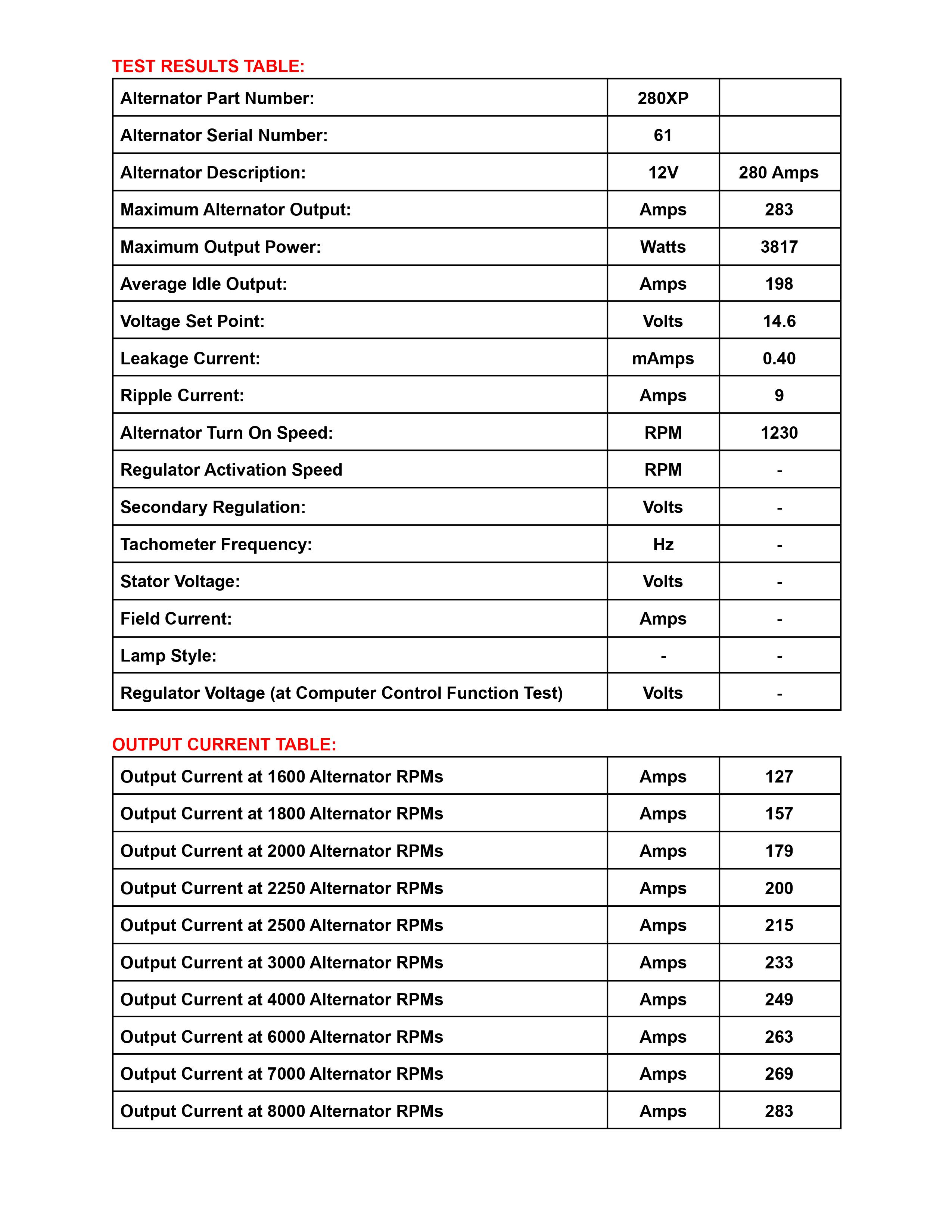
A 12 V auxiliary alternator rated 280 A, added alongside the vehicle's original alternator so it can charge the house bank while the factory unit carries on running the vehicle. Nations' test sheet records 283 A maximum output, 3,817 W, an average idle output of 198 A, a 14.6 V set point and a turn-on speed of 1,230 rpm; the output-versus-speed table reads 127 A at 1,600 alternator rpm, 200 A at 2,250, 233 A at 3,000, and reaches the full 283 A only at 8,000. Those are bench figures indexed to alternator rpm rather than engine rpm; Vanlife Outfitters, which builds these systems, reports 120 to 150 A at engine idle and 200 to 250 A on the road.

Nations sells the 280XP in two forms, and they wire differently. The SE version has an internal regulator that comes on by stator signal once the engine is running, and is sold for AGM banks. The ER version has no internal regulator at all — an external Balmar or Wakespeed unit drives its field — and that is the one sold for lithium.

Wiring it

There is one stud to land a cable on — B+ here, "the alternator output stud" in Nations' own guide. It runs to the house bank's positive distribution, not to the starter battery: the whole point of the second alternator is that it serves a bank the vehicle doesn't. There is no matching negative stud. The alternator is case-grounded, so the return cable lands on one of the mounting-bracket bolts, which is what makes people ask whether the part needs a negative cable at all.

It does. Nations' van installation guide sizes the return exactly like the charge lead — 2/0 welding cable for runs under 20 feet, 4/0 over 20 feet, for the output and the ground alike — and asks for that ground run all the way back to the battery distribution rather than picked up on the frame, in its words because frame grounds are problematic. Their universal high-output guide is blunter still: upgrading the return path is not an optional step. The alternator's fuse goes at the distribution end near the battery, not at the alternator; Nations sizes it at 125 % of maximum output.

An ER alternator charges nothing until the external regulator is wired to it. That is a field wire to the field lead on the alternator plug, a temperature-sensor lead to the connector on the alternator case, a battery temperature sensor on a negative post at the bank, current-sense wires at the shunt, and an ignition wire on a circuit that is live only while the engine runs. The regulator's own power and sense wire is fused — 15 A on Nations' Wakespeed van harness — and lands on the alternator side of the main cable fuse, so it reads alternator voltage rather than battery voltage if that fuse ever opens.

What people get wrong

Using the battery disconnect switch to shut the alternator off. Nations' van instructions say service cut-off switches must not be turned off while the vehicle is running, and that doing so may damage the alternator. Balmar's MC-618 manual makes the same point from the regulator's side: if the sense wire is reading battery voltage after the alternator has been disconnected from the battery, the regulator keeps driving output, likely causing alternator damage, and that damage is not covered under warranty.

The same fault arrives by a quieter route when the regulator or the BMS is fed from a switched circuit rather than the main positive bus. One Sprinter owner on Sprinter-Source describes an upfitter who wired it that way and blew the diode bridge in an alternator before rewiring those feeds. Charging is stopped at the regulator's ignition wire — a toggle on that circuit costs nothing and gives you an off switch that cannot hurt anything.

Supporting parts

  • A return cable the same size as the charge cable, run back to the battery distribution rather than terminated on the frame
  • A fuse at the distribution end of the charge cable, at the bank rather than at the alternator; the 280XP van builds documented on Sprinter-Source use Class T or MRBF holders there
  • An external regulator for the ER version (Balmar MC-614 / MC-618 or Wakespeed WS500), with its alternator and battery temperature sensors
  • A shunt the regulator can read, when the regulator uses current sensing
  • An ignition-switched feed for the regulator, with a toggle so charging can be stopped without opening the battery switch

Build it out

Connect it to the rest of your system.

Add 280XP to your diagram, then connect your batteries, chargers and loads. Crimp calculates cable sizes and checks the connections as you draw.

Every cable you draw there is sized against ABYC E-11, from the same tables as the reference on this page.

Technical reference

Specifications, terminals and supporting parts.

Check the model, ratings and connection points against your own unit before choosing installation hardware.

Catalog specification

Rated output
280 A
Planning charge current
200 A

Supporting parts

  1. 20 ft total of 3/0 AWG (95 mm²) marine cable
  2. Terminations for 3/0 AWG cable, matched to the equipment's screw terminals, leads or studs
  3. 350 A fuse and holder on the positive run
  4. Heat-shrink, strain relief and terminal boots sized to the cable

Check stud sizes, fuse type, run length and how warm the space gets against the gear you actually have before you order.

Terminal map

Catalog connection points, current direction and planning limits. Check the manufacturer's pinout and connector ratings before installation.

B+

pos

positive · output

350 A

GND

neg

ground · bidi

350 A

Method & provenance

Where the specifications and sizing come from.

Manufacturer specifications describe the equipment. Crimp calculates cable results from the circuit and assumptions you enter.

From the maker

What the catalog says

Manufacturer, model, ratings and which terminal does what come from the catalog. A newer revision, or the nameplate on the unit in your hand, can say something different — when it does, the nameplate wins.

ABYC E-11

What Crimp worked out

Sized against ABYC E-11 — the US reference, and what Transport Canada accepts as an alternative to TP 1332 for pleasure craft under 24 m. The run length and the current above are what drive the result. Crimp doesn't know how warm your space gets; draw the cable inside an engine-bay zone on the canvas and it sizes for the heat.

Read how the sizing works

Next step

Plan your installation with 280XP 280A.

Open this example as a new project. Add your equipment and cable lengths, then review the sizing and checks for your setup.